Edit Radar for Current Site
After adding a radar to an area of the current site, you can edit the parameters of the radar, including map settings, zone settings, camera calibration, and event settings.
Make sure you have configured GIS map. See Set GIS Map and Icons for details about configuring GIS map.
-
In the area list panel, select the added current site from the drop-down site
list to show its areas.
Note:
The icon
 indicates that the site
is current site.
indicates that the site
is current site. -
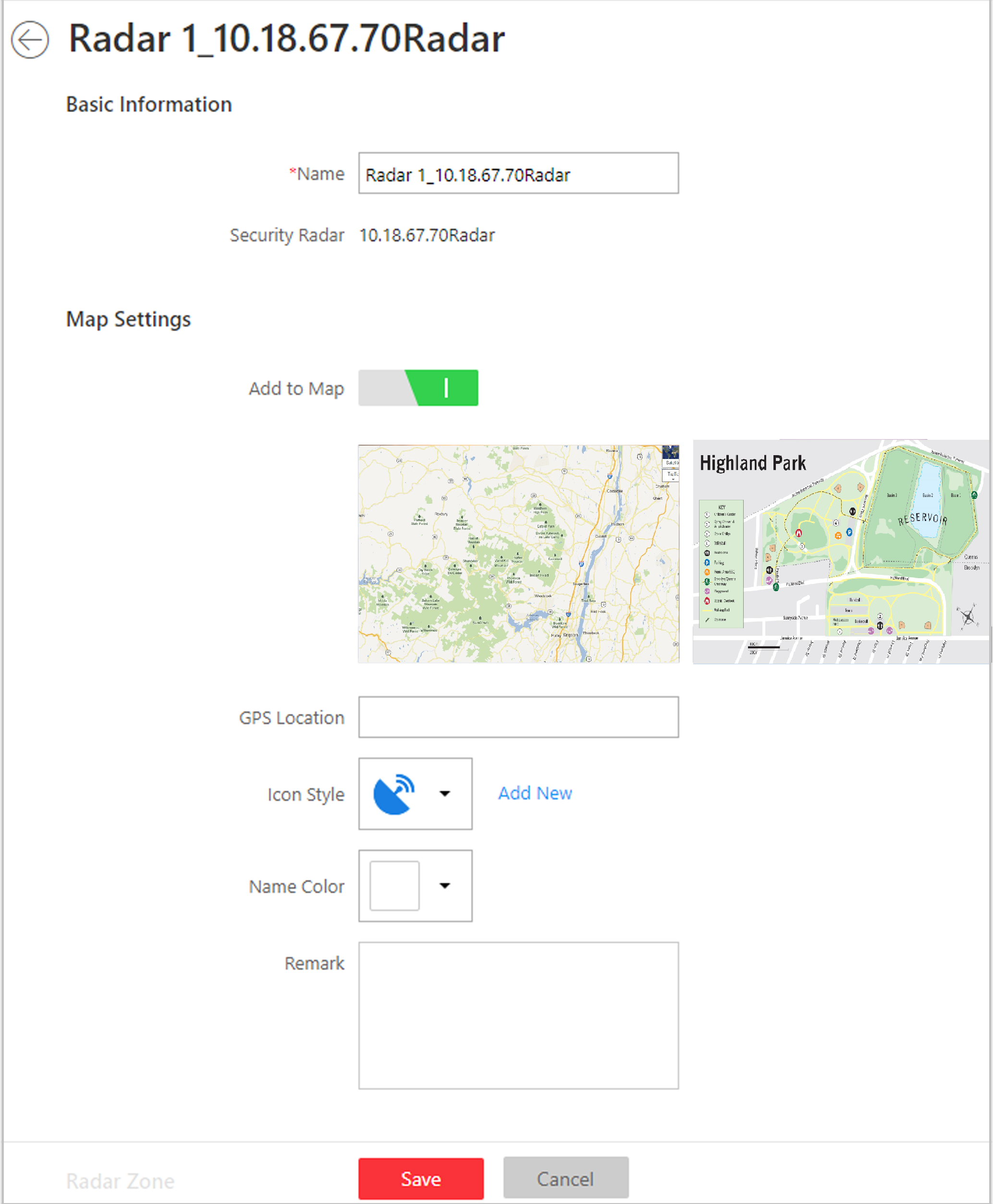
Edit Map Settings.
Figure 1. Edit Radar Page
-
Configure radar zone.
-
Select a zone drawing method in the tool bar in the upper-left corner
of the map.
Figure 2. Tool Bar for Drawing Zone

 Draw Trigger
Line
Draw Trigger
Line-
A trigger line is a virtual line drawn in the radar's detection area. An event or alarm will be triggered if an object is detected to have crossed the line. Click to draw a trigger line in the detection area. Select a direction for the trigger line. The three directions indicate three directions to which a detected object crosses the line. You can drag the anchor (the red point on the trigger line) to reshape the trigger line, or drag the trigger line to move it to another place.
Note:No more than 4 trigger lines can be drawn.
Figure 3. Trigger Line in the Detection Area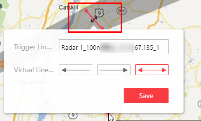
 Draw
Dual-Trigger Line
Draw
Dual-Trigger Line-
A dual-trigger line consists of 2 virtual lines drawn in the radar's detection area. Generally, it is used to mark an area in the radar's detection area. An event or alarm will be triggered if an object is detected to have entered the area shaped by the dual-trigger line. Click to draw a dual-trigger line in the detection area. Select a direction for the trigger line. The three directions indicate three directions to which a detected object crosses the line. You can drag the anchor (the red point on the trigger line) to reshape the dual-trigger line, or drag the dual-trigger line to move it to another place.
Note:Only 1 dual-trigger line can be drawn in the radar's detection area.
Figure 4. Dual-Trigger Line in the Detection Area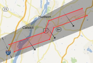
 Manually
Draw
Manually
Draw-
You can draw any shape for the zone using this method.
 Zone
Segmentation
Zone
Segmentation-
Split a zone into two smaller zones by a line.
Figure 5. Zone Segmentation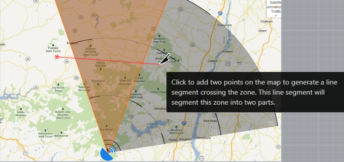
 Distance
Segmentation
Distance
Segmentation-
Split a zone into two smaller zone by an arc.
Figure 6. Distance Segmentation
 Field
Assistance
Field
Assistance-
Click to enable zone painting assistance function. For example, person A takes an on-site walk along the field to shape a closed figure as a zone. And then the moving path will automatically be painted as a zone on the map and a window for selecting zone type will pop up. And then Person B which operating the computer running the Web Client select a type for the zone.
-
Select a zone drawing method in the tool bar in the upper-left corner
of the map.
-
Set related calibrated camera(s) for radar.
Note:
This operation requires two persons' teamwork: person A walks into the radar's detection area (the person's position will be displayed on the map as a red point
 ), while person B who
operates the computer running the Web Client adds calibration points by
PTZ control of the calibrated camera(s) according to person A's
position.Figure 7. Add Calibration Point Window
), while person B who
operates the computer running the Web Client adds calibration points by
PTZ control of the calibrated camera(s) according to person A's
position.Figure 7. Add Calibration Point Window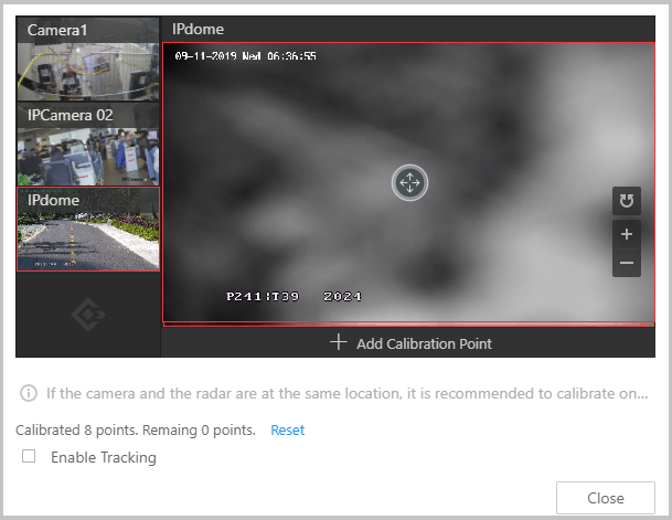
-
Person A goes to the location which can be detected by one of the
calibrated cameras. Person B clicks
 in the Operation
column.
in the Operation
column.
Person A's location will appear on the map as a red point
. -
Click to open the adding
calibration point window.
The calibrated cameras' thumbnails will be displayed on the left.
-
Close the Add Calibration Point window and click
 to save the
settings.
to save the
settings.
-
Person A goes to the location which can be detected by one of the
calibrated cameras. Person B clicks
Edit Radar for Current Site
After adding a radar to an area of the current site, you can edit the parameters of the radar, including map settings, zone settings, camera calibration, and event settings.
Make sure you have configured GIS map. See Set GIS Map and Icons for details about configuring GIS map.
-
In the area list panel, select the added current site from the drop-down site
list to show its areas.
Note:
The icon
indicates that the site
is current site. -
Edit Map Settings.
Figure 1. Edit Radar Page
-
Configure radar zone.
-
Select a zone drawing method in the tool bar in the upper-left corner
of the map.
Figure 2. Tool Bar for Drawing Zone
- Draw Trigger
Line
-
A trigger line is a virtual line drawn in the radar's detection area. An event or alarm will be triggered if an object is detected to have crossed the line. Click to draw a trigger line in the detection area. Select a direction for the trigger line. The three directions indicate three directions to which a detected object crosses the line. You can drag the anchor (the red point on the trigger line) to reshape the trigger line, or drag the trigger line to move it to another place.
Note:No more than 4 trigger lines can be drawn.
Figure 3. Trigger Line in the Detection Area
- Draw
Dual-Trigger Line
-
A dual-trigger line consists of 2 virtual lines drawn in the radar's detection area. Generally, it is used to mark an area in the radar's detection area. An event or alarm will be triggered if an object is detected to have entered the area shaped by the dual-trigger line. Click to draw a dual-trigger line in the detection area. Select a direction for the trigger line. The three directions indicate three directions to which a detected object crosses the line. You can drag the anchor (the red point on the trigger line) to reshape the dual-trigger line, or drag the dual-trigger line to move it to another place.
Note:Only 1 dual-trigger line can be drawn in the radar's detection area.
Figure 4. Dual-Trigger Line in the Detection Area
- Manually
Draw
-
You can draw any shape for the zone using this method.
- Zone
Segmentation
-
Split a zone into two smaller zones by a line.
Figure 5. Zone Segmentation
- Distance
Segmentation
-
Split a zone into two smaller zone by an arc.
Figure 6. Distance Segmentation
- Field
Assistance
-
Click to enable zone painting assistance function. For example, person A takes an on-site walk along the field to shape a closed figure as a zone. And then the moving path will automatically be painted as a zone on the map and a window for selecting zone type will pop up. And then Person B which operating the computer running the Web Client select a type for the zone.
-
Select a zone drawing method in the tool bar in the upper-left corner
of the map.
-
Set related calibrated camera(s) for radar.
Note:
This operation requires two persons' teamwork: person A walks into the radar's detection area (the person's position will be displayed on the map as a red point
), while person B who
operates the computer running the Web Client adds calibration points by
PTZ control of the calibrated camera(s) according to person A's
position.Figure 7. Add Calibration Point Window
-
Person A goes to the location which can be detected by one of the
calibrated cameras. Person B clicks in the Operation
column.
Person A's location will appear on the map as a red point
. -
Click to open the adding
calibration point window.
The calibrated cameras' thumbnails will be displayed on the left.
-
Close the Add Calibration Point window and click to save the
settings.
-
Person A goes to the location which can be detected by one of the
calibrated cameras. Person B clicks