Terminal Description
Terminals
Figure 1 Main Unit Terminals
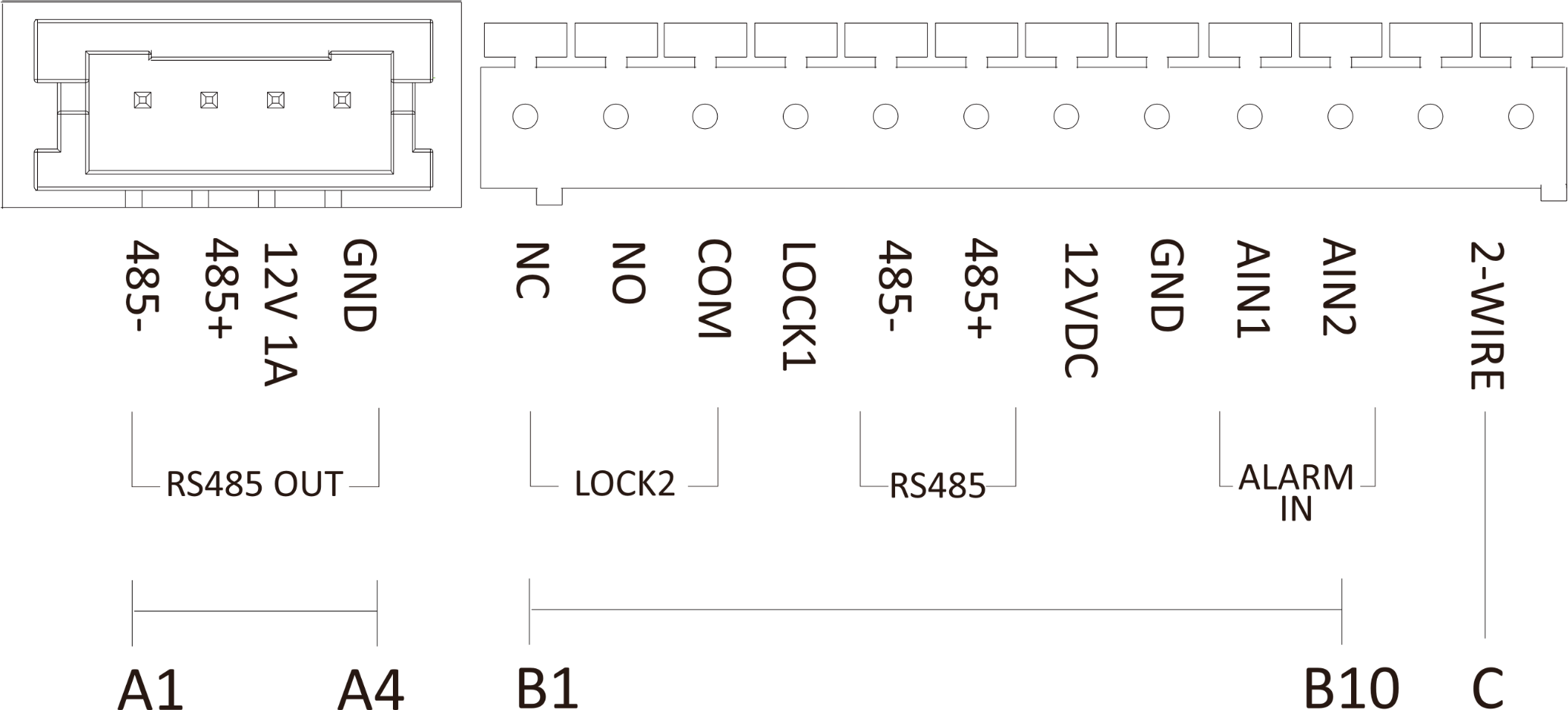
|
No. |
Interface |
Description |
|---|---|---|
|
A1 |
485- |
Module-connecting Interface |
|
A2 |
485+ |
|
|
A3 |
12V 1A |
|
|
A4 |
GND |
|
|
B1 |
NC |
Door Lock Relay Output (NC) |
|
B2 |
NO |
Door Lock Relay Output (NO) |
|
B3 |
COM |
Common Interface |
|
B4 |
LOCK1 |
Door Lock Interface |
|
B5 |
485- |
Reserved |
|
B6 |
485+ |
|
|
B7 |
12VDC |
12 V power input |
|
B8 |
GND |
Grounding |
|
B9 |
AIN1 |
Exit Button 1 (for unlocking door 1) |
|
B10 |
AIN2 |
Exit Button 2 (for unlocking door 2) |
|
C |
2-WIRE Interface |
2-Wire Interface |
Wiring
Figure 2 Wiring of Door Station
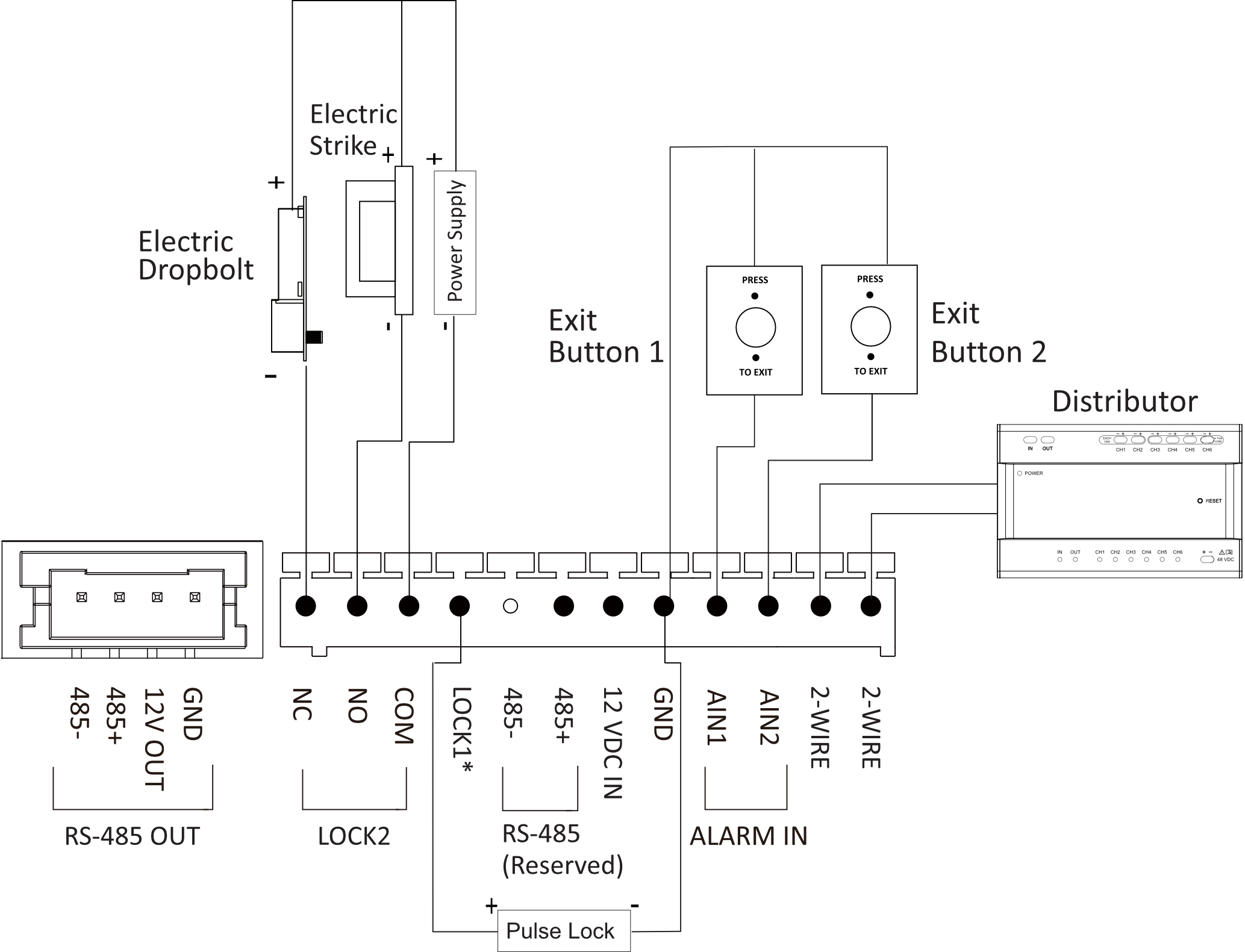
Note:
-
LOCK 1 is an 20 V/4 A impulse output with 300 mA holding current.
-
The Exit Button 1 is for unlocking door 1; The Exit Button 2 is for unlocking door 2.