Configure Network Switches
Introduction
After you add and activate network switches together with AC routers on the Mobile Client, you can configure network switches including rebooting devices, restarting ports, configuring VLANs, and check the cable status.
Supported Devices
Refer to the device compatibility list for the supported models.
Configure VLAN

-
Tap in the upper right corner of the switch detail page, and then tap VLAN.
-
Create a VLAN on your switch.
-
Tap .
-
Select an adding mode.
-
Set the VLAN ID to identify and differentiate VLANs within a Layer 2 network domain, and tap Save.
Note-
The maximum number of VLANs that can be added in a batch varies with device models.
-
VLAN ID 1 and 4095 are typically reserved for special purposes. VLAN ID 1 is typically used for the default VLAN. Most switches are assigned to the default VLAN by default if no other VLAN is specified. VLAN ID 4095 is reserved for the use of VLAN trunking protocols. It is not used for regular VLAN traffic.
-
-
-
Assign ports to the VLAN to enable logical segmentation of the network.
-
Tap Configure, and select the desired ports.
NoteThe VLAN configuration is not allowed for ports in an aggregation group. Aggregation groups, also known as link aggregation or port trunking, are used to combine multiple physical ports into a single logical port to increase bandwidth and provide redundancy.
-
Select a port VLAN type.
NotePort Type
Description
Following Operation
ACCESS
Used to connect devices that need to connect devices that need to communicate within a single VLAN. An access port is like a door that leads directly into a specific room (VLAN). When you enter through that door, you can only communicate with the people inside that room. For example, if you have an access port assigned to VLAN 10, any device connected to that port can only communicate with other devices.
None
TRUNK
Used to connect devices that need to communicate with multiple VLANs. A trunk port is like an elevator in the building. The elevator can carry people (data) to multiple rooms (VLANs) based on the floor (VLAN tag) they want to go to. For example, if you have a server that needs to communicate with devices in VLANs 10, 20, 30, you would connect the server to a trunk port. The trunk port would carry traffic for all the three VLANs, and the VLAN tags in the data packages would help the switch determine which VLAN the traffic belong to.
Set the accessible VLANs. For example, consider a switch with VLANs 10, 20, and 30. If you have a trunk port connecting to a server, you might only want the server to communicate with devices in VLANs 10 and 20, but not VLAN 30. In this case, you would configure the trunk port to have VLANs 10 and 20 as accessible VLANs, while excluding VLAN 30.
-
Set the PVID (Port VLAN ID) to ensure untagged traffic is routed to the correct VLAN, and tap Save.
NoteThe PVID is used to used to determine which VLAN an incoming packet belongs to when the packet does not carry any VLAN tag. In simpler terms, the PVID is the default VLAN assigned to a switch port. When a device connected to that port sends a packet without a VLAN tag, the switch will associate the packet with the VLAN specified by the PVID. For example, consider a switch with VLANs 10, 20, and 30. If you have a port connected to a device that doesn't support VLAN tagging, you can assign a PVID to that port. If the PVID is set to VLAN 10, any untagged traffic received on that port will be considered part of VLAN 10 and forwarded accordingly.
-

Other Operations
|
Operation |
Description |
|---|---|
|
Reboot Switch |
Tap to reboot the switch. |
|
View Peer Device |
Tap Device to view the details of the device connected to this port. |
|
Clear Alarm |
For port with alarm(s), tap > Clear Alarm to clear the alarm(s) of this port. |
|
Restart Port |
For the abnormal port, tap > Restart Port to restart this port. |
|
Enable/Disable Extend Mode for Port |
Tap Enable Extend Mode/Disable Extend Mode to extend or not to extend the transmission range of this port. Note
After enabled, the transmission range of the port will be extended to 200 to 300 m. Meanwhile, its bandwidth will be limited within 10 Mbps. |
|
View Cable Status |
Tap > Cable Detection, tap a port, and then tap Detect. When the detection is finished, you can view the detection result and cable length. |
|
Check Receiving/Sending Rate |
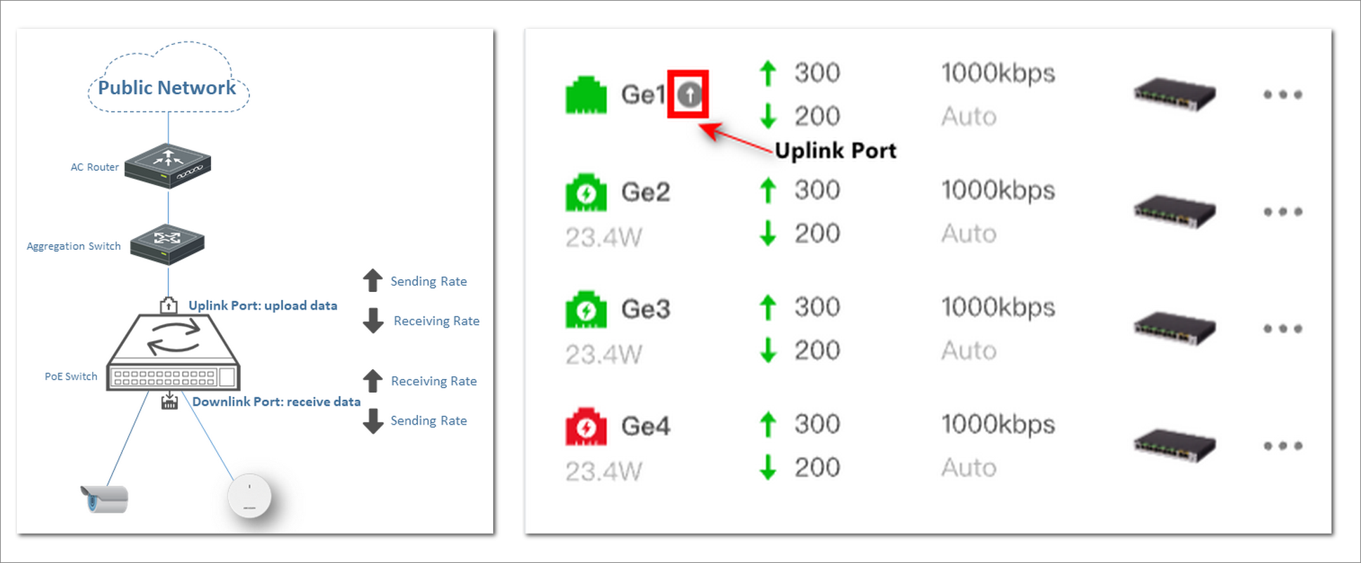
For switches and AC devices, the receiving rate for an uplink port is the downlink rate, while the sending rate is the uplink rate. For downlink ports, the receiving rate is the uplink rate, and the sending rate is the downlink rate. For details, see the following picture. |


Operations on Network Topology
-
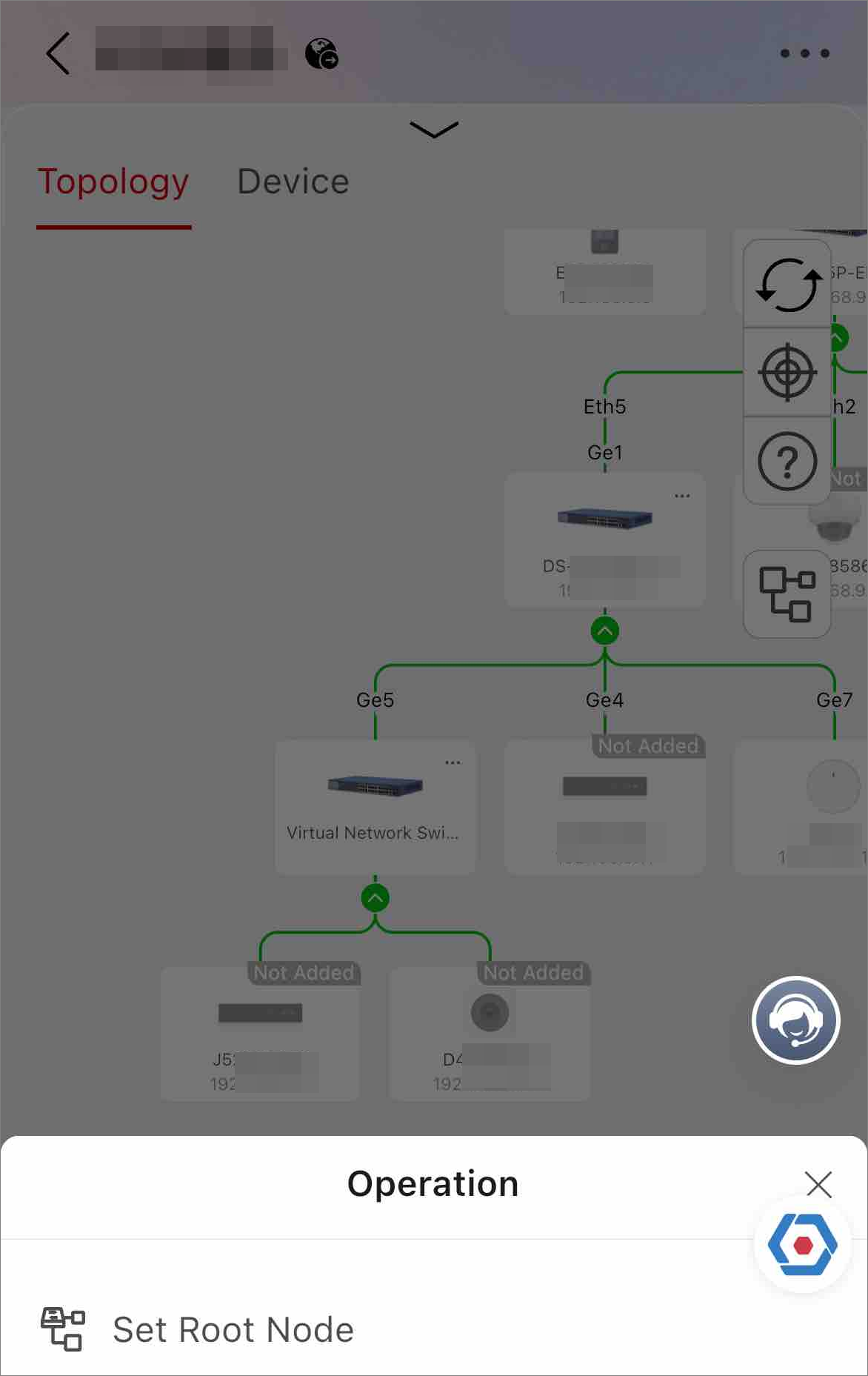
Set an AC to the root node.
Figure 3 Set Root Node -
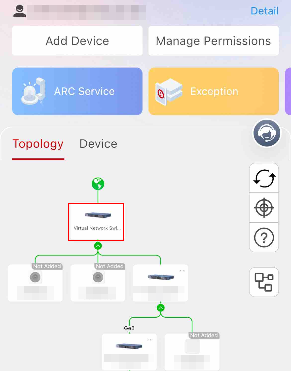
Set a third-party switch (referred as virtual network switch) to the root node on the Mobile Client.
Figure 4 Set Virtual Network Switch to Root Node