Configure Parameters for Access Control Devices and Elevator Control Devices
You can configure parameters for access control devices and elevator control devices, including device time, linkage settings (linked device actions), maintenance settings, etc.
In the top left corner of Home page, select > Basic Management > Device.

On thel left of the Device module, select Access Control Device or Elevator Control Device, and click in the Operation column to enter the configuration page of a device.
 in the Operation column to enter the configuration page of a
device.
in the Operation column to enter the configuration page of a
device.Configure device parameters according to the following topics.
-
Device support required. Parameters vary with different device types and models.
-
The supported features and parameters are subject to the applications you installed.
Time
You can view the time zone where the device locates and set the following parameters.
Biometrics
You can enable facial recognition and fingerprint recognition of access control devices if the devices support biometrics recognition.
Skin-surface Temperature
Set Temperature Measurement to on to enable temperature screening function.
- Threshold(℃)
-
Set the range of normal skin-surface temperature. The detected temperature that is not in this range is abnormal temperature. The maximum temperature should be higher than the minimum temperature.
- Open Door When Temperature is Abnormal
-
If it is enabled, the door will open when person's skin-surface temperature is abnormal. By default, the door will not open for abnormal temperature.
- Linked Thermal Camera
-
Enter the device IP address of the linked thermal camera for temperature screening.
NoteIt is used for the access control devices that do not support temperature screening.
Registration Device
If you enable this function, the information about added persons and credentials (including face pictures and fingerprints) added on the device will be automatically synchronized to the platform.
Mask Settings
Set Mask Detection to on to enable mask detection function. Once enabled, the device can detect persons without face masks.
RS-485
Turnstile Parameters
You can configure passing mode for the turnstile linked to the device.
- Based on Lane Controller's DIP Mode
-
The device will follow the lane controller's DIP settings to control the turnstile. The settings on the main controller will be invalid.
- Based on Main Controller's Settings
-
The device will follow the settings of main controller to control the turnstile. The DIP settings of the lane controller will be invalid.
Maintenance
You can reboot a device remotely and restore it to its default settings.
Facial Recognition Mode
You can check Deep Mode to enable the function. Once enabled, all the face credentials applied to the device will be cleared. Go to and click to apply the data in the platform to the device.

More
You can click Configure to open the remote configuration page of the device and configure more parameters. For details, refer to the user manual of the device.
Configure Relations Between Relays and Floors
You can configure the relations between relays and floors to determine how floor control is managed, including options such as passengers selecting target floors, passengers calling elevators, or automatic floor button pressing and elevator summoning for passengers.
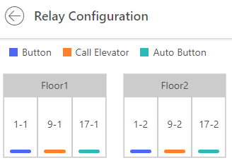
There are three types of relay available.
- Button
-
Control the validity for buttons of each floor. For floors related to Button, passengers can press the button of the floors.
- Call Elevator
-
Control to call the elevator to go to the specified floor. For floors related to this feature, people who are waiting for elevators can call elevator to the floor they stay.
- Auto Button
-
Control to press the button when the user swipes card inside or outside of the elevator. The button of the floor will be pressed automatically according to the user's permission.
Configure the relations between the relays and the floors.
-
Drag the unconfigured relay from the Unconfigured Relay panel to the target floor.
-
Drag the relay from the Floor List panel to the Unconfigured Relay panel.
-
Drag the relay from one floor to another floor in the Floor List panel. If the target floor has already configured with a relay of the same type as the dragged one, it will replace the existed one of the same type.
Take the following picture as an example. In the number 1-2, 1 represents the distributed elevator controller number, 2 represents number of the relay, and the color under the number represents the relay type.
Custom Wiegand Parameters
Based on the knowledge of uploading rule for the third-party Wiegand, you can configure Wiegand parameters to communicate between the device and the third-party card readers.
-
By default, the device disables the custom Wiegand function. If you enable the custom Wiegand function, all Wiegand ports in the device will use the customized Wiegand protocol.
-
You can configure up to 5 custom Wiegand devices.
Switch on Custom Wiegand and configure the Wiegand parameters. You can select a device from the Copy From drop-down list to copy the settings of another device.
- Total Length
-
Wiegand data length.
- Parity Type
-
Set the valid parity for Wiegand data according to property of the third party card reader. You can select Nothing, Odd Even Check, or XOR Parity.
If you select Odd Even Check, you can configure the following:- Odd Start, Length
-
If the odd parity start bit is 1 and the length is 12, then the platform will start odd parity calculation from bit 1. It will calculate 12 bits. The result will be in bit 0 (Bit 0 is the first bit).
- Even Start, Length
-
If the even parity start bit is 12, and the length is 12, then the platform will start even parity calculation from bit 12. It will calculate 12 bits. The result will be in the last bit.
If you select XOR Parity, you can configure the following:- XOR Parity Start Bit, Length per Group, Length for Parity
-
Depending on the table displayed below, the start bit is 0, the length per group is 4, and the length for parity is 40. It means that the platform will calculate from bit 0, calculate every 4 bit, and calculate 40 bits in total (10 groups in total). The result will be in the last 4 bits (The result length is the same as the length per group).
- Output Rule
-
Set the output rule.
- Card ID Start Bit, Length, and Decimal Digit
-
If you use the transformation rule, these items are available. Depending on the table displayed below, the card ID start bit is 0, the length is 32, and the decimal digit is 10. It represents that from bit 0, there are 32 bits represent the card ID. (The length here is calculated by bit.) And the decimal digit length is 10 bits.
- Site Code Start Bit, Length, and Decimal Digit
-
If you use the transformation rule, these items are available. For detailed information, see the explanation of the card ID.
- OEM Start Bit, Length, and Decimal Digit
-
If you use the transformation rule, these items are available. For detailed information, see the explanation of the card ID.
- Manufacturer Code Start Bit, Length, and Decimal Digit
-
If you use the transformation rule, these items are available. Depending on the table displayed below, the manufacturer code start bit is 32, length is 8, and decimal digit is 3. It represents that from bit 32, there are 8 bits are manufacturer code. (The length here is calculated by bit.) And the decimal length is 3.
Take Wiegand 44 for example, the setting values in the Custom Wiegand are as follows:
|
Custom Wiegand Name |
Wiegand 44 |
||||
|
Total Length |
44 |
||||
|
Transformation Rule (Decimal Digit) |
byFormatRule[4]=[1][4][0][0] |
||||
|
Parity Type |
XOR Parity |
||||
|
Odd Parity Start Bit |
Length |
||||
|
Even Parity Start Bit |
Length |
||||
|
XOR Parity Start Bit |
0 |
Length per Group |
4 |
Total Length |
40 |
|
Card ID Start Bit |
0 |
Length |
32 |
Decimal Digit |
10 |
|
Site Code Start Bit |
Length |
Decimal Digit |
|||
|
OEM Start Bit |
Length |
Decimal Digit |
|||
|
Manufacturer Code Start Bit |
32 |
Length |
8 |
Decimal Digit |
3 |
Set Wiegand Parameters
You can set Wiegand parameters for access control devices to facilitate communications between card readers and access control devices.
Select a Wiegand protocol in the list, and click in the Operation column to pop up a window of Wiegand information. On the pop-up window, set Wiegand parameters and click OK.
 in the Operation column to pop up a window of Wiegand
information. On the pop-up window, set Wiegand parameters and click
in the Operation column to pop up a window of Wiegand
information. On the pop-up window, set Wiegand parameters and click
- Direction
-
Whether the device is used for inputting (receiving) or outputting (sending) data.
Check Input or Output.
- Wiegand Mode
-
The signal transmitting mode. Whether the device transmits 26-bit, 34-bit, 27-bit, and 35-bit data.
NoteWiegand mode can only be selected when the direction is Output.
- Output Format
-
Whether to output the signal as employee No. or card No.
NoteOutput format can only be selected when the direction is output.
- Signal Sending Interval
-
The interval of sending data.
- Linked Card Reader
-
The card reader No. to be linked.
NoteLinked card reader can only be selected when the device supports linking to a card reader.
Configure Device Actions
You can set the linkage actions of an access control device or elevator control device for different event sources, so that when the device detects a linkage source, the device can execute actions such as capturing a picture, triggering alarm output, triggering buzzer, locking/unlocking access point, etc.
Click Add in the Linkage section. Set the event source, and then configure parameters of the linkage target.
- Buzzing
- Capture/Recording
- Alarm Output
- Zone
- Access Point
-
- Unlock
-
Unlock the door or barrier when the specified event is triggered.
- Lock
-
Lock the door or barrier when the specified event is triggered.
- Remain Unlocked
-
The door or barrier will remain unlocked when the specified event is triggered.
- Remain Locked
-
The door or barrier will remain locked when the specified event is triggered.
- No Linkage
-
Disable the linkage action.
- Floor
-
- Temporary Access
-
Grant access to the floor for a limited time when the specified event is triggered.
- Access with Credential
-
Grant access to the floor if the user presents valid credentials when the specified event is triggered.
- Free Access
-
Grant access to the floor indefinitely when the specified event is triggered.
- Access Forbidden
-
Deny access to the floor indefinitely when the specified event is triggered.
- No Linkage
-
Disable the linkage action.
Card Swiping Parameters
You can configure card swiping parameters to allow authentication by entering card number on keypad, enable NFC clone card, enable M1 encryption, etc.
In Card Swiping section, configure card swiping parameters.
- Reader Communication Protocol
-
Select the reader communication protocol.
- Input Card Number On Keypad
-
If it is checked, users can enter card number on keypad for authentication.
- Enable NFC Card
-
If it is enabled, users can use cloned cards for authentication.
- M1 Encryption
-
If it is enabled, only the card with the same encrypted sector can be granted access, and you need to choose an encrypted sector.
- Voice Prompt
-
If it is enabled, an audio prompt will be played when swiping cards.
- Upload Picture after Linked Capture
-
Upload the pictures captured by the linked camera(s) to the platform automatically.
-
- Picture Storage
-
If it is checked, the captured pictures will be automatically saved to the storage location you configured in picture storage settings for the access points.
NoteFor details about configuring picture storage settings, see Edit Door for Current Site or Edit Elevator for Current Site.
- Picture Size
-
Select a picture size from the drop-down list for the captured pictures saved to the storage location.
- Picture Quality
-
Select a picture quality from the drop-down list for the captured pictures saved to the storage location.
- Capture Times
-
Select the capture times from the drop-down list for the devices to capture face pictures for the times selected.